
We specialise in Desk Studies, Geotechnical and Geo-environmental Ground Investigations, associated Laboratory Testing and provision of Professional Reports. Giving clear and concise recommendations based on the investigation findings.

Phase 1
Walkover Survey & Desk Study
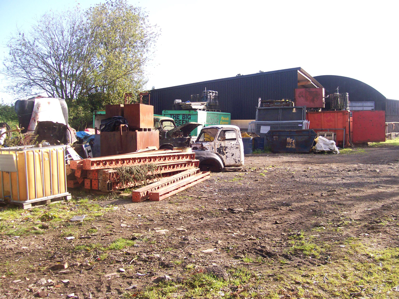
A Walkover Survey is a key part to the Phase 1 Desk Study and includes a visit to undertake a visual assessment of the site and its immediate surroundings.
Photographs are usually taken and any potential ground problems or contamination sources identified during this reconnaissance which may not be evident from the historical map search.
These can include, for example, above and below ground tanks, asbestos containing materials and any ground stability issues. The Desk Study should be carried out as the preliminary stage of any investigation and is typically required to satisfy planning conditions. The aim is to formulate an initial conceptual site model (CSM), which highlights the potential sources of contamination, receptors and the pathways between them. This “conceptual model” is critical in designing an appropriate Phase 2 intrusive investigation. However, it should be recognised that both phases of investigation are commonly combined into a single contract in order to save time and reporting expenses for our clients.
Under current legislation the provision of a desk study is typically a minimum requirement when submitting a planning application. The presence of contamination is a concern for the regulatory bodies when considering development proposals. The developers have an obligation to comply with the environmental regulations at each step of the planning, design and construction process, and the local planning authorities have a duty to ensure any investigation and remedial work is carried out in accordance with current guidance to an acceptable level. An environmental risk assessment is a key element in the initial stages of this process. The Desk Study Report follows the recommendations in EA Contaminated Land Report 11 (CLR 11) and EA Guidance on Requirements for Land Contamination Reports.

A comprehensive report will commonly provide the following datasets:
- Ordnance Survey, Town Plans and Aerial Photographs to allow us to assess existing and former land uses
- Initial simple flood risk potential by reference to Environment Agency mapping and British Geological Survey records
- Solid and drift geology by reference to British Geological Survey mapping and borehole index Groundwater vulnerability from Environment Agency classification of aquifer status Consultation with local authority Environmental Unit (if applicable)
- Assessment of potential subsidence issues from examination of geological maps, boreholes index and Brine Subsidence search for sites within relevant areas
- Active and historical surface and underground workings based upon published information and internal records
- Coal Authority Mining Report if site is within Mining District
- Active and closed landfill search within 500m of the site boundary based upon local authority and Environment Agency records Active and closed landfill search within 250m of the site boundary based upon local authority and Environment Agency records
- Radon gas potential with reference to Heath Protection Agency records.
- It should be noted that Limited Desk Studies are designed for geo-environmental purposes only and do not include Structural Surveys, Buried Services Surveys, above ground or building Asbestos Surveys, Unexploded Ordnance Surveys or Invasive Plant Surveys for Japanese Knotweed, Giant Hogweed, Planning History, Archaeological Assessments, Planning,vHistory, Ecological Assessments etc. Preliminary Archaeological Assessment based on reference to National Monument Records
Phase 2
Site Investigation
Please select a service from the menu options below.
Standard Cable Percussion Rig
 Site Investigation fieldwork is frequently carried out in the U.K. using a cable percussion drilling rig to obtain engineering information on ground conditions and samples for subsequent laboratory analysis.
Commonly, depths of up to 30-35m can be achieved. As an example only - a 10 to 15 metre deep, 150mm diameter, borehole will normally take 1 day to complete.
In-situ testing and sampling can include Standard Penetration Tests (SPT’s), undisturbed samples (U100’s) along with disturbed, bulk and water samples as necessary.
The precise location of each borehole is often decided on site, in order that boreholes are located to cause least disturbance to other activities in the area and so that services may be avoided. All borehole locations are checked with a Cable Avoidance Tool (CAT).
Cable percussion boreholes are drilled using a Dando 150 cable percussion boring rig, or similar, operated by a two-man crew and all borehole arisings are normally removed from site.
The rig is towed behind a 4-wheel drive Land Rover or similar and is self-contained. During site operations there will be a certain amount of noise from the diesel engine and intermittent noise from the drilling process.Work is normally undertaken under the direction of a qualified geotechnical engineer who may attend during site operations.
Tracked Percussion Rig
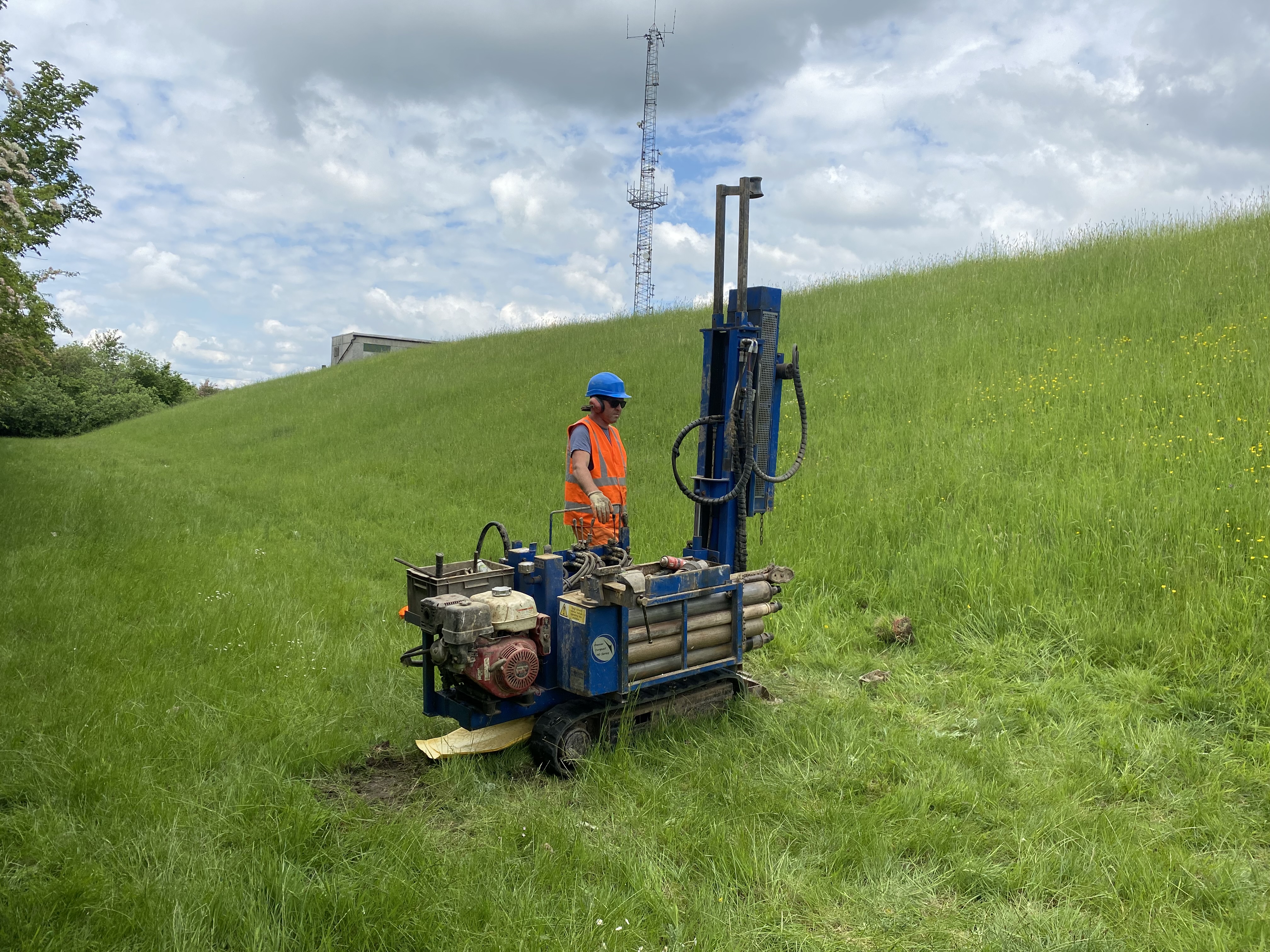 When access for a standard cable percussion rig is not available or when the depth of geotechnical information required is 15 metres or less and ground conditions are suitable then the Premier Tracked Rig can be employed.
In-situ penetration testing and sampling can include Standard Penetration Tests (SPT’s), along with disturbed samples as necessary. These can be re-moulded to allow for 38mm triaxial tests to be undertaken.
The SPT comprises a weight of 63.6 kg dropping through a free-fall height of 762mm in accordance with British Standard BS 1377 : Part 9. The weight drives a 50mm diameter “split-spoon” sampler into the ground. The resistance to penetration is recorded for 6 consecutive 75mm increments with the SPT ‘N’ value calculated from an addition of the final four 4 readings.
The rig is brought to site within a large Transit Van and is self-contained and self-erecting. The sampling tube, including a 98mm diameter casing system is driven into the ground with a series of 1 metre long metal tubes. The sampling tubes can be driven through the casing to obtain disturbed samples at regular depth intervals and vary in diameter from 80mm to 35mm.
During site operations there will be a certain amount of noise from the diesel engine and intermittent noise from the drilling process.
Window Sampler
 The window sampler (also known as the Drive-in-Sampler) is a lightweight portable boring equipment, ideal for shallow boreholes with limited access.
The drive-in-sampler boring technique can commonly drill down through concrete and brick overburden and superficial made ground to a depth of 5-7 metres below existing ground level. In ideal conditions depths of up to 10m can be achieved.
The technique is therefore very useful in Subsidence and Contamination sampling situations. An added advantage is that the technique does not arouse as much interest from the general public or create the damage and remedial/reinstatement works that trial pitting does when, for example, excavating through existing tarmac car parks etc.
The drive-in-sampler comprises a series of 1 metre and 2 metre long, 100mm to 35mm diameter, tubes that are driven into the ground using a mini-hydraulic breaker. The tubes are subsequently jacked out of the ground and side windows enable the tubes to be cleaned and small disturbed samples to be taken.
During site operations there will be a certain amount of noise from the hydraulic power pack and breaker unit as the sample tubes are driven into the ground. The precise location of the boreholes is often decided on site, in order that they may be situated so that they cause least disturbance to other activities in the area and that services may be avoided.
Trial Pitting
 Mechanically-Excavated Trial Pits
 Mechanically-Excavated Trial Pits
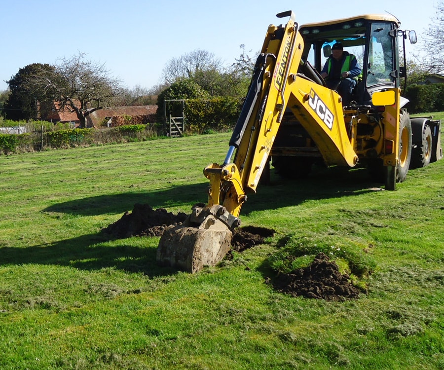
Trial pitting is often carried out using a JCB type wheeled mechanical excavator complete with a hammer breaker attachment if required.
Work is undertaken under the supervision of a qualified geotechnical or geo-environmental engineer at all times.
No excavations are left unattended when open and once information has been gained from each excavation this is normally backfilled. Where access is restricted, for example rear gardens to residential properties, smaller "mini-excavators" can be employed.
 Hand-Excavated Trial Pits
 Hand-Excavated Trial Pits
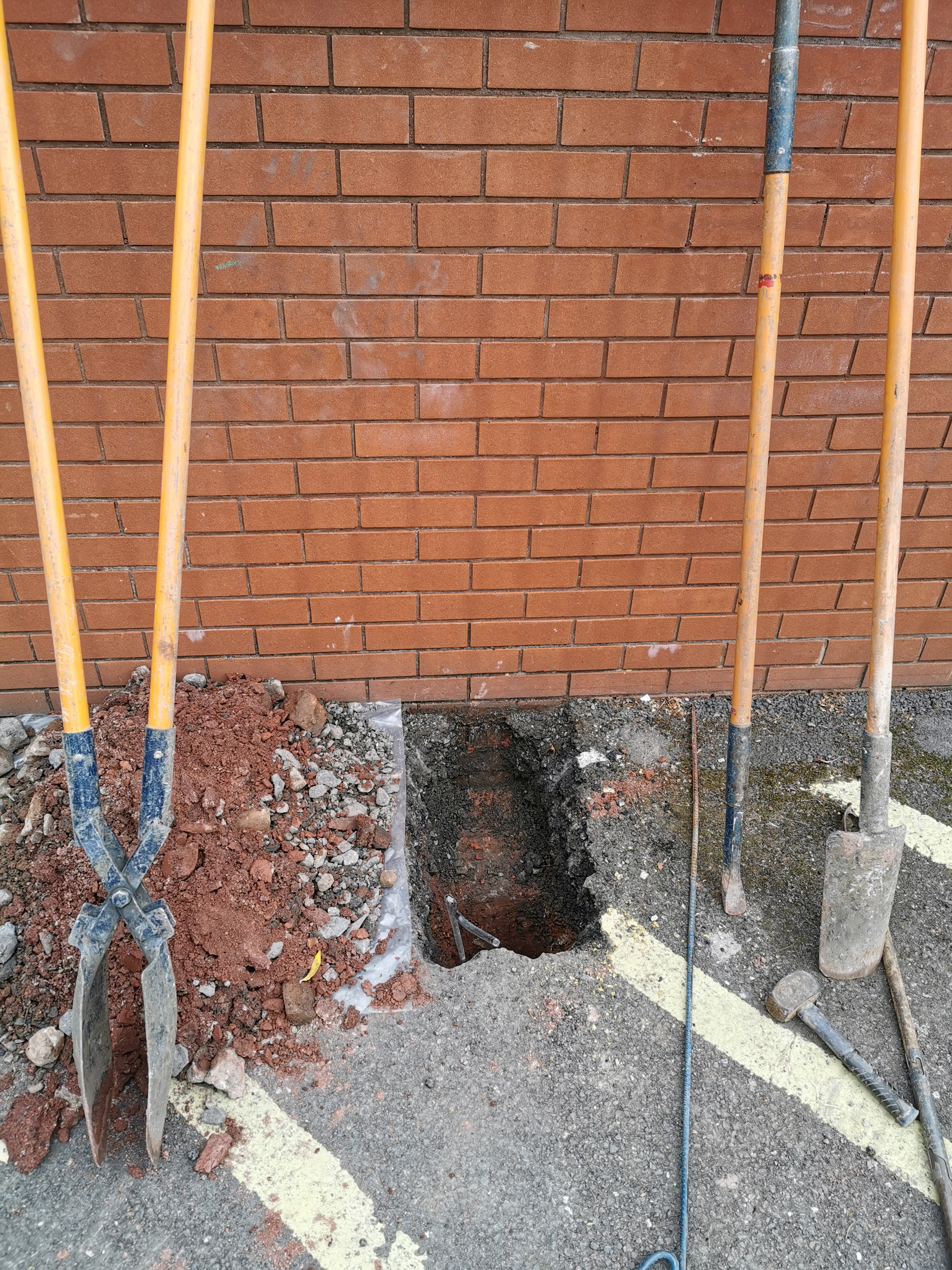
When access does not allow for a JCB or ‘mini-excavator’ Trial Pits can be hand-excavated up to a maximum depth of 1.20m. This will commonly reach underside of foundations and is very useful in sensitive areas where known services are located.
In-situ Shear Vane tests can be performed in open Trial Pits in order to provide quick shear strength results of soil. It is not recommended, for the purposes of foundation design, that Shear Vane values replace those from conventional triaxial tests.
Dynamic Probing
 The Dynamic Probe operated by Risk Management Limited is classed as a Dynamic Probe “Heavy” (DPH) in accordance with BS 5930:2015 “Code of Practice for Site Investigations”.
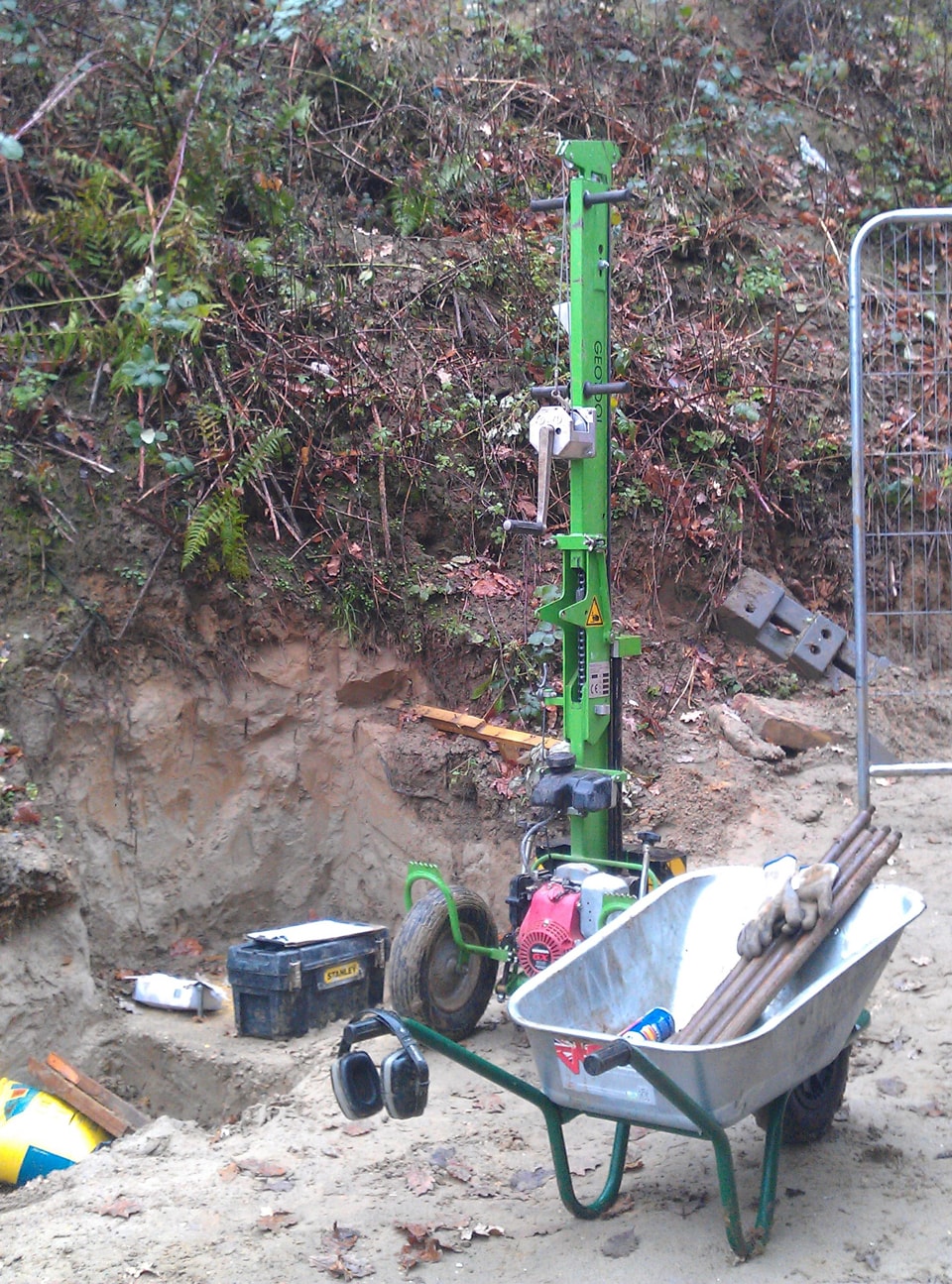
The Dynamic Probe is hinged for easy transport and access to site.
Height when extended: 2.34m Width: 0.78m Length: 0.785m Total weight approx: 360 kg
The Dynamic Probe uses the 50 kg weight dropped in “free-fall” from a fixed height of 500mm to drive a 15cm2 cone into the ground.
The number of blows per 100mm is recorded and the resulting blow counts can be used to obtain equivalent Standard Penetration Test (SPT) ‘N’ values.
Approximate ‘Equivalent’ SPT ‘N’ Values can be determined by dividing the cumulative blow counts for each 300m of penetration by 1.5 as recommended by Card and Roche. The results are presented as plots of blow counts versus depth.
During site operations there will be noise from the continuous blows to the top of the drive rods.
Gas/Groundwater Monitoring Installations (Standpipes)
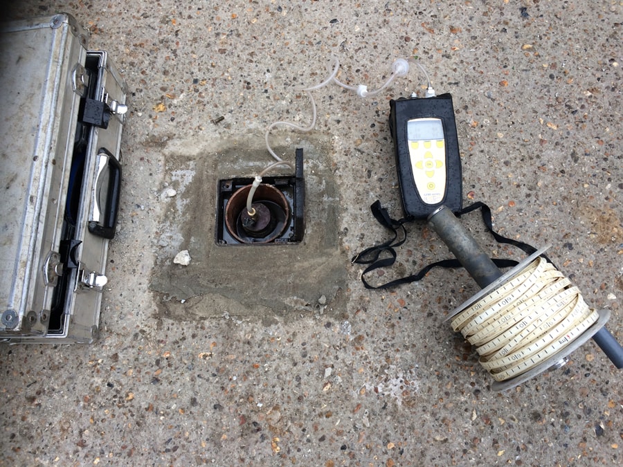 On completion of a borehole, gas and groundwater monitoring installations can be installed comprising 50mm or 19mm diameter (depending on plant used) HDPE slotted and plain casing as necessary wrapped in a geotextile sock to prevent silting up and finished at ground surface with a lockable stopcock cover, concreted in flush with the existing ground surface.
A cement/bentonite seal is normally installed from 1.00m to ground level and the installation finished with a gas valve on top of the pipe and a lockable stopcock cover concreted in flush with ground level.
Gas monitoring of carbon-dioxide, methane, oxygen and flow levels can be recorded and together will provide a Gas Screening Value (GSV) and a classification in accordance with CIRIA Publication C665 “Assessing Risks Posed by Hazardous Gases to Buildings (Revised 2007)” and/or the NHBC “Traffic Light” System.
Laboratory Testing
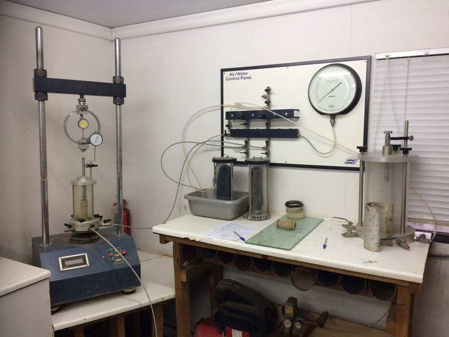 Geotechnical Testing is undertaken at Risk Management Limited on-site laboratory in Godalming, Surrey. All geotechnical testing is generally undertaken to BS 1377 1990, “Methods of Test for Soils for Civil Engineering Purposes”.
Contamination and Chemical Testing is carried out in accordance with standard industry methods in a UKAS approved laboratory which is also currently accredited in accordance with MCERTSfor the majority of its testing.
Further information regarding this accreditation is available on request together with a full list of test methods if required.
A list of the typical geotechnical and contamination testing we undertake is as follows;
- Atterberg Limits and Moisture Content Tests
- Triaxial Shear Strength Tests (100mm and re-moulded 38mm)
- Particle Distribution Analysis
- Organic Content
- Root Identification
- pH and Water Soluble Sulphate
- Contamination testing including speciated PolyAromatic Hydrocarbon (PAH) and speciated Total Petroleum Hydrocarbon (TPH), together with BTEX, Benzene, Toluene, Ethylbenzene and Xylenes
- Waste Acceptance Criteria (WAC) tests
- This is not an exhaustive list of the testing we can undertake so please contact us if you have any special requirements.
Soakage and Permeability Tests
 There are a number of ways of assessing whether the ground would be suitable for soakaways or superficial SUDS type drainage schemes. The tests effectively determine the permeability of the soil so that soakaways can be designed for the required flow rate and frequency of use.
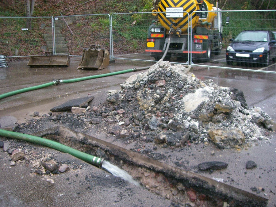
BRE 365 Soakage Test
Soil Infiltration Tests are carried out in a machine excavated trial pit in accordance with the methods described in BRE Digest 365 “Soakaway Design”. Trial pit dimensions are recorded and the sides of the trial pit kept as vertical as possible.
The trial pit is then filled with water as quickly as possible and the time noted for the start of the test. Water is usually supplied from a 2000 gallon lorry-mounted tanker situated close to the excavation and water pumped through a short length of pipe directly into the trial pit. The time and depth from ground level to water surface is then recorded at regular intervals as the water level falls within the trial pit over three periods.
Following the test a Soil Infiltration Test Rate (f) can be calculated.
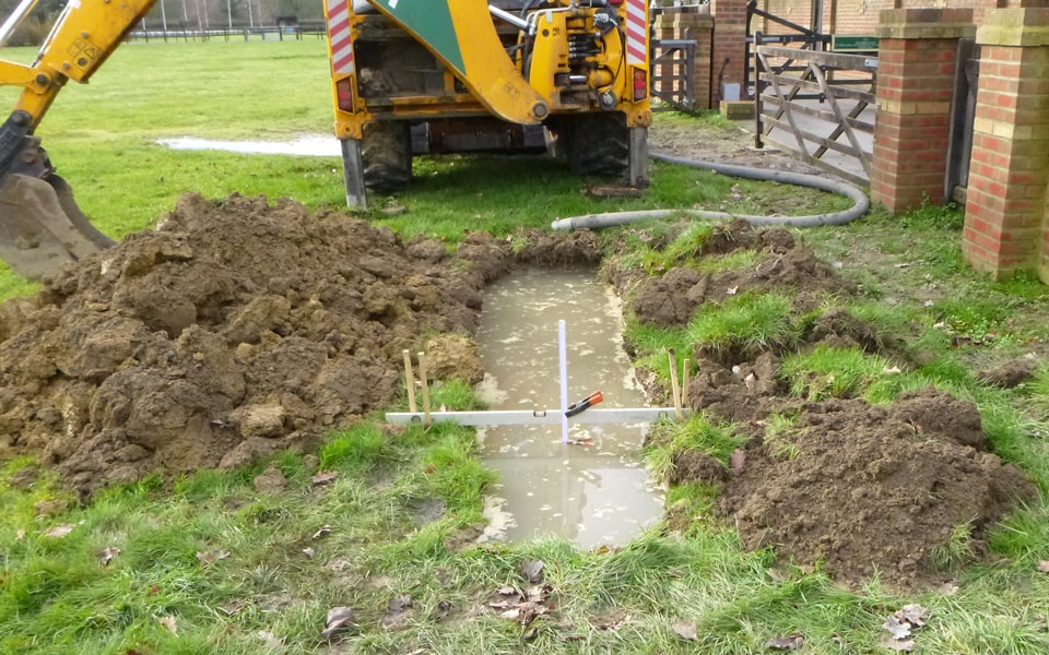
BRE 365 ‘Truncated’ Soakage Test
Where access is restricted, truncated Soil Infiltration Tests can be carried out within a trial pit excavated by a mini-digger or by hand. The tests are carried out in accordance with the methods described in BRE Digest 365 “Soakaway Design”, but modified based on the advice given in Section H2 of Building Regulation Approved Document H “Drainage and Waste Disposal” 2002.
Once the trial pit is excavated a 300mm x 300mm square section is excavated by hand at test level. This section is then filled with water and the time for water to drain away three times noted. Again, a Soil Infiltration Test Rate (f) can be calculated.
Falling Head Permeability Tests
Falling head permeability tests can be undertaken within borehole installations in accordance with B.S.5930:2015 Part 25.4.3 Variable Head Test. A permeability rate (k) can then be calculated which will give an indication of whether a Borehole Soakaway installation will be successful on site.
Drainage Test
Drainage Percolation Tests can be carried out in accordance with BS 6297:2007 to determine average Vp values to enable treated effluent units to be designed.
The tests are carried out within a trial pit excavated by a mini-digger or by hand. Once the trial pit is excavated a 300mm x 300mm square section is excavated by hand at test level. This section is then filled with water and the time for water to drain away three times noted.
Other Specialist Techniques
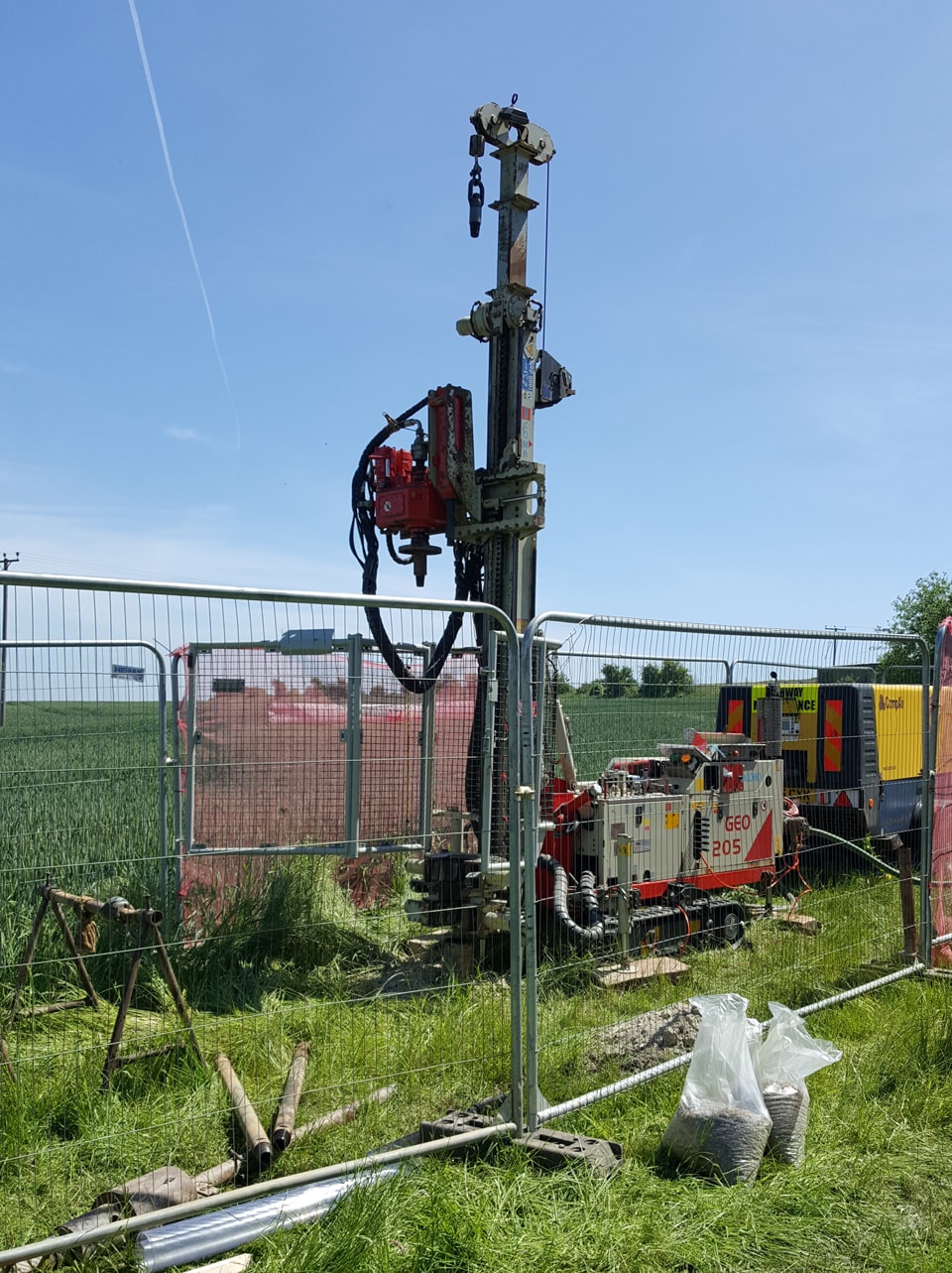
Rotary Drilling
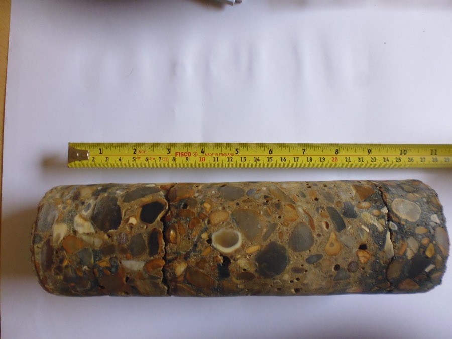
Where hard rocks such as Mudstone and Sandstone, or some soft rocks, such as Chalk are encountered then rotary drilling may be required.
A variety of drilling rigs are available depending on site access and depth of borehole required. The photographs on this page show a small selection of the drilling rigs available for rotary drilling to depths in excess of 100m if required.
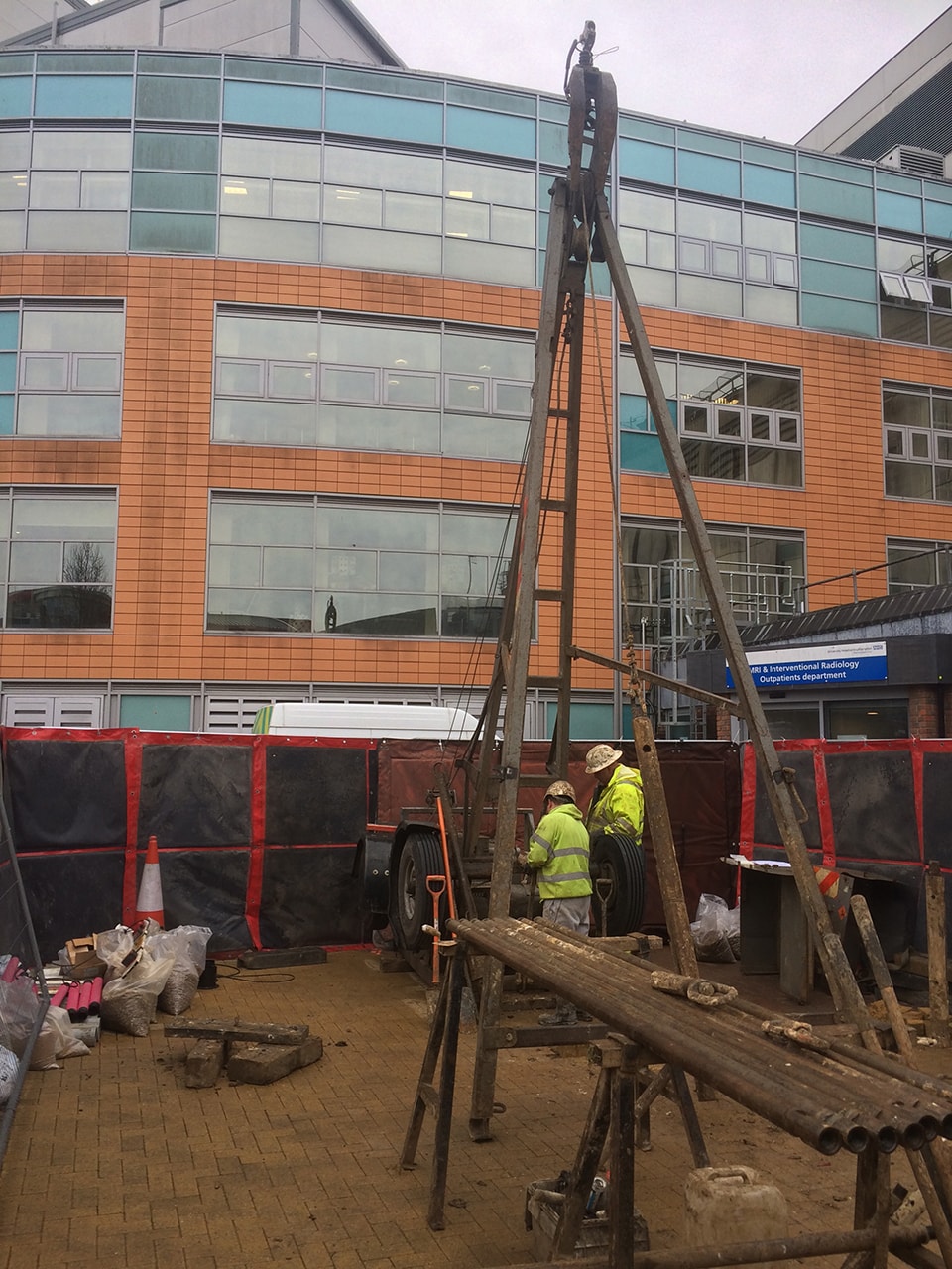
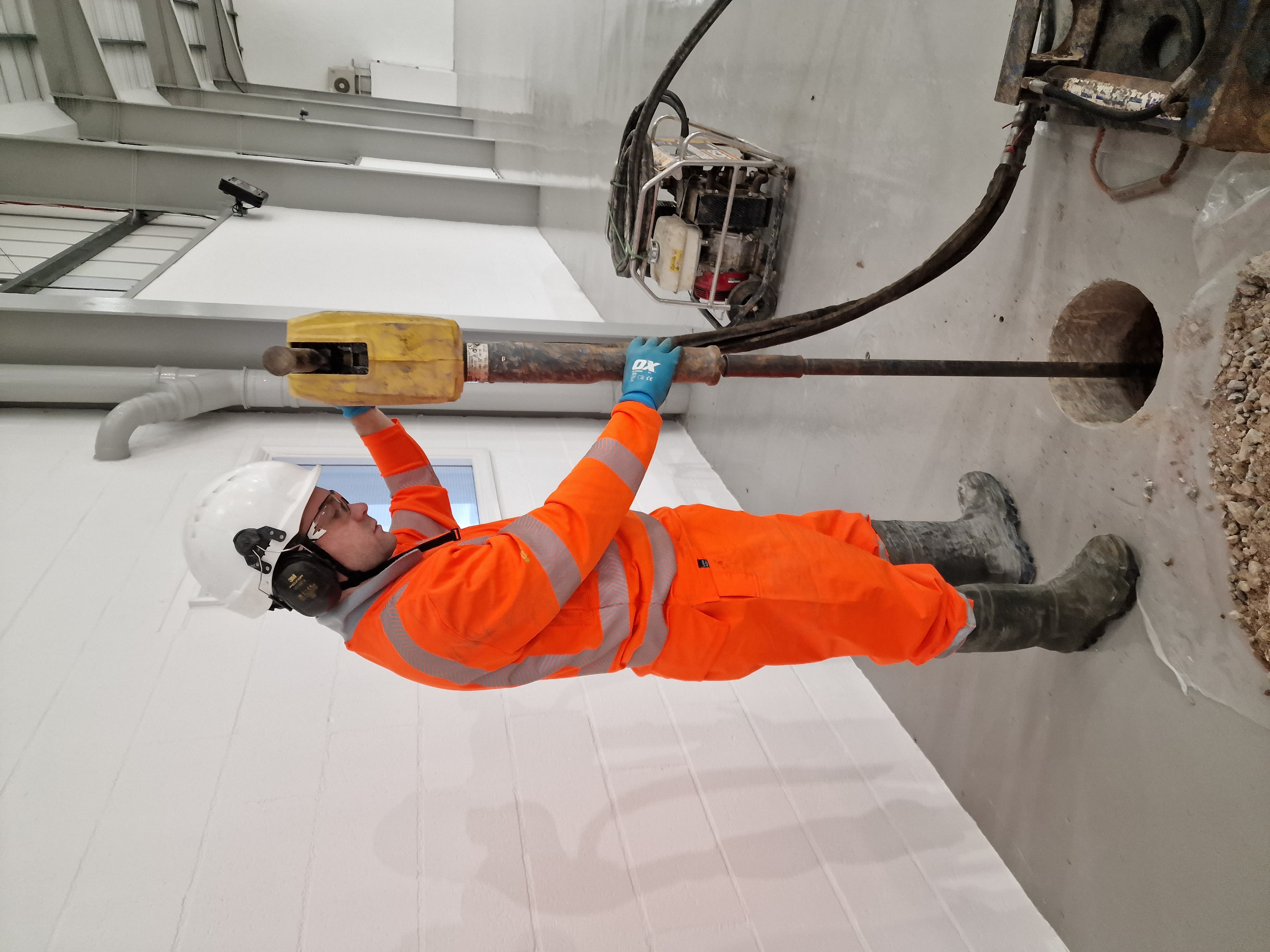
Low Headroom
Where access is restricted or drilling from within building and/or basements is required then specialist low-headroom "cut-down" drilling rigs can be employed. These are specifically designed to be dismantled and passed through narrow openings, down stairs etc. and then re-assembled. Variable length drilling legs are utilised to undertake this work depending on the headroom available.
Concrete Coring
Where concrete slabs need to be penetrated out prior to drilling the quickest and most-effective way is by employing a concrete coring machine. Core sizes can vary from 50mm up to 200mm.
California Bearing Ratio (CBR)
For the purposes of road design California Bearing Ratio (CBR) information can be recorded using a MEXE Probe. The MEXE Probe consists of a cast aluminium housing containing a calibrated compression spring, operating shafts and dials with a CBR cone. The instrument is forced into the ground and an average of the readings obtained is considered the CBR value.
Phase 3 & 4: Remediation & Verification
Remediation
Following on from completion of the Phase II, Intrusive, Site investigation and recommendations, a Phase III Remediation Method Statement (RMS) may be required. This generally sets out what action is required in order to make the site suitable for use and provides details on how such works will be carried out and validated.
Recommendations will usually need to be reviewed by the regulators involved in the project, which will typically include the Environment Agency, the local planning authority and any warrantors for the scheme.The RMS confirms the work carried out to date together with the recommended methods for remediation to be carried out during the construction period.
Any documentation and information required to be collated as the scheme progresses, such as waste tickets from Landfill operators, gas membrane installation details etc., are listed within the RMS and collated at the end of the project in a Validation Report.Where practicable, applicants are encouraged to arrange pre-application discussions with the Local Planning Authority and statutory consultees (Environment Agency and Environmental Health section) in order for any requirements to be considered and incorporated into the development proposals at an early stage.
Verification
On completion of the remedial works, the developer/main contractor will be required to submit a Validation Report, sometimes known as a Completion or Verification Report, to confirm that all necessary remediation works have been carried out in accordance with the agreed Phase III Remediation Method Statement.
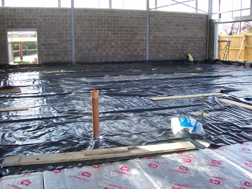
Where protection measures, for example installation of a methane gas membrane, are required, supporting information regarding the successful installation and appropriate verification will be required.In addition, “check” testing of samples of imported ‘clean’ material and topsoil are often also required.